Bearings in planetary gears, hydraulic pumps and other assets are frequently exposed to conditions where elastic deformations in their surrounding parts, such as shaft bending, lead to significant misalignment of the rings towards each other. Such misalignment results in local pressure peaks and an associated reduction of bearing life. Proper raceway crowning lessens these effects and is therefore a highly relevant consideration during supplier approval.
The influence of local stresses can be considered during the design process but also needs to be taken into account during testing if bearing performance is to be verified on a test rig. Here, the acceleration of test runs can complicate the situation. Typically, test loads are higher than application loads because years of service life must be represented by weeks on a test bench. When investigating the effect of misalignment, the chosen testing conditions must lead to non-uniform stress distributions similar to those expected in the application.
When testing, the degree of misalignment can be controlled with the use of customized fixtures. However, it is always important to verify that the test conditions adequately mimic the application. The FVA Workbench is a powerful tool that can calculate local stresses both for the application and the test case. This article shall show a general approach to testing for applications where significant misalignment in the bearings is expected.
Download “Properly considering the influence of shaft bending when testing bearings” as a PDF.
Find all of our articles here.
Endurance testing is a powerful method for verifying bearing performance and approving the related supplier. However, one of the challenges during testing is modelling years of service life as weeks of endurance on a test rig without altering the conclusions. Typically, speed and loads are the parameters that control testing time. Higher speeds allow thesame number of revolutions to be reached within a shorter time, but also alter the lubrication conditions. These changes can be compensated for by changing the lubricant viscosity.
Increasing the loads also helps to reduce testing time. However, overdoing this can cause problems to arise on the test rig that may be completely irrelevant in the field. For applications characterized by a broad spectrum of loads such as passenger cars, where peak torque only accounts for a small percentage of the operating time, testing can be accelerated by focusing on the maximum normal loads while ignoring the time consuming “cruising” conditions.
If, however, misalignment needs to be considered in addition to loads and speed, one must pay particular attention to the local stresses. The crowning of raceways can be optimized for a particular amount of tilting and a specific load. If the testing conditions exceed those of the real application, the amount of shaft bending can be higher as well and potentially lead to face edge contact on the test rig that would not appear in the application. Consequently, a potentially good supplier might not be considered qualified because the testing data was generated under unsuitable conditions.
This makes it desirable to be able to calculate the local stress distributions for both the application and test setup in order to ensure that the testing data adequately represents the real-world conditions. The FVA Workbench is a powerful tool capable of simulating numerous real-world applications and their potential test setups, including determining a feasible fixture design to achieve the necessary shaft bending.
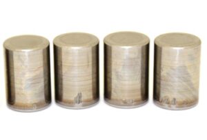
During a recent testing project, a full complement of roller bearings subject to a significant amount of misalignment due to shaft bending in the application were to be tested. In order to choose the testing conditions, the raceway profiles were measured and then used to calculate the pressure distributions and bearing life in the application according to ISO 26281.
This article will give a brief overview of the test rig before introducing the FVA Workbench simulations and finally reviewing their conclusions compared with experimental data.
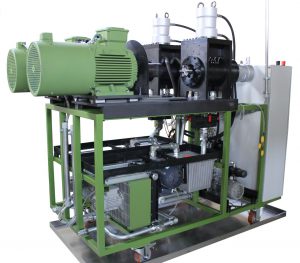
Tests were carried out on an EELPRAAX-130 test rig (Figure 1) built by Elgeti Engineering GmbH. The EELPRAAX line of test rigs can apply axial, radial, or combined loads and are available in different sizes to accommodate bearings up an outer diameter of 320 mm. Like all Elgeti Engineering test rigs, they feature two fully independent stations on the same frame.
A custom-built fixture is used to fit the bearings into the housing. The shaft and motor are connected by a double cardanic coupling which is resistant to minor misalignments and dampens vibrations. The motor and test head are mounted on a stiff base plate that is connected to the main frame with vibration dampers. These eliminate the influence of external vibrations, particularly those from the opposing test station.
The test rig features an oil circulation lubrication system with a variable flow rate. Oil temperature determines the operating temperature of the bearings and is measured at the test head inlets and outlets and adjusted with a cooler; heating is optionally available, but typically not needed. The standard oil filter has a 10μm mesh; a finer mesh is also optional. Loads are applied with controlled hydraulic cylinders, making it possible to apply not only constant loads, but also ramps, steps, and cycles.
Measured quantities include the outer ring temperature of all the bearings, the housing vibrations, and the motor torque. These quantities are used to detect a bearing failure and trigger an automatic shutdown. This allows the machine to run continuously without supervision.
Misalignment is controlled by the shaft design, i.e. the degree of shaft bending permitted. Both the diameters of the shaft and the distance between bearings define the bending line. During the design process, one must remember that bearings increase the stiffness of the shaft and that a proper simulation in the FVA Workbench is essential for generating the desired results.
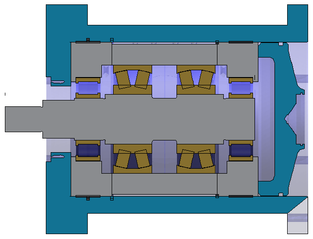
The FVA Workbench is a powerful tool for designing and analyzing mechanical systems involving bearings and gears at both the component and system level. In order to recreate the testing environment outlined above, a CAD model of the test head was imported to the workspace and the tooling and bearings modelled into it (Figure 2). The appropriate materials were assigned to the tooling and housing. The lubricant type and temperature, loads, andspeed were selected to correspond to the initial testing parameters; they can be further refined based on the simulation results.
The FVA Workbench allows the user to choose bearings from a library, import an XML-file from the manufacturer, or define them directly. Regardless of which option is chosen, one can apply either default of user-defined crowning profiles; user-defined profiles can, for example, be based on measurements of the bearings in question. In this case, the major geometry was specified based on drawings from the manufacturer and the crowning profile was specified based on measurements.
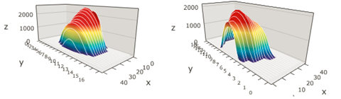
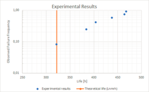
Figure 4 shows the local stress distributions at testing conditions that are representative of the real application, including the correct amount of shaft bending. Based upon these simulation results, the test runs were performed using the same parameters. The measured lifetimes are overall higher than the calculated lifetime (Figure 5). The bearings in question therefore fulfill the requirements and the supplier was approved.
The approach followed here – utilizing simulations to inform test parameter selection – ensures that testing conditions are actually representative of the particular application characteristics, without exaggeration or underestimation. This is especially important when, as in this application, significant misalignment between the bearing rings is expected.


Elgeti Engineering GmbH · Aachen · Germany
Elgeti Engineering USA Inc · Valparaiso, IN · USA
Copryright 2026 @ Elgeti Engineering GmbH